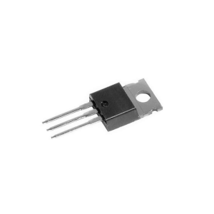
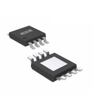
Innledning 12V amplifier ICs are essential components in various audio applications, from car audio systems to portable speakers. These integrated circuits offer a compact, efficient way to amplify audio signals, making them a popular choice for both hobbyists and professionals. Optimizing these circuits for maximum performance involves careful selection of components, precise gain settings, efficient power supply design, effective thermal management, noise reduction techniques, and strategic circuit layout. This guide will walk you through each of these elements, providing practical tips and tricks to help you get the best performance out of your 12V amplifier circuits.

1. Understanding 12V Amplifier ICs
What are 12V Amplifier ICs?
12V amplifier ICs are integrated circuits designed to amplify audio signals with a 12-volt power supply. These ICs are widely used in audio applications due to their efficiency and ability to deliver high-quality sound output in a compact form factor. Popular 12V amplifier ICs include the LM386, TDA2030, and TDA7377, each offering different features and performance characteristics.
For a detailed overview of various 12V amplifier ICs and their applications, you can visit Texas Instruments.

Why Use 12V Amplifier ICs?
The use of 12V amplifier ICs in audio applications is driven by several advantages:
- Efficiency: These ICs can deliver substantial power output with minimal energy loss.
- Compactness: The integration of multiple functions into a single chip reduces the overall circuit size.
- Allsidighet: Suitable for a wide range of audio applications, including automotive, portable, and home audio systems.
- Ease of Use: Simplified circuit design and implementation, making them accessible even for beginners.
For more on the benefits and applications of 12V amplifier ICs, check out this comprehensive guide by Analoge enheter.
2. Choosing the Right Components
Key Factors in Component Selection
Selecting high-quality components is crucial for optimizing your 12V amplifier circuit. Poor-quality components can degrade performance and reduce the lifespan of your circuit. Key factors to consider include:
- Tolerance and Precision: Components with tight tolerance and high precision ensure consistent performance.
- Thermal Stability: Components should be able to withstand the thermal stresses of the circuit.
- Frequency Response: Choose components that match the desired frequency response of your amplifier.
Capacitors and Resistors
Capacitors and resistors play vital roles in shaping the signal and controlling the gain in amplifier circuits. Key considerations include:
- Capacitors: Use high-quality electrolytic and ceramic capacitors for filtering and decoupling. The value of the capacitor affects the frequency response and stability of the amplifier.
- Resistors: Precision resistors with low tolerance (1% or better) are recommended for setting gain and biasing the circuit.
For a deeper dive into selecting capacitors and resistors, you can explore resources from Electronics Tutorials.
Transistors and Inductors
Transistors are the core amplifying elements in many ICs, while inductors can be used for filtering and impedance matching. Consider the following:
- Transistors: Ensure the transistors used within the IC are rated for the expected voltage and current levels. Look for low-noise transistors for better audio quality.
- Inductors: Use inductors with appropriate current ratings and low DC resistance to minimize losses.
For more information on transistor and inductor selection, refer to the guides available on All About Circuits.

3. Setting the Gain
Understanding Gain Control
Gain is a measure of how much an amplifier increases the strength of a signal. Proper gain control is essential for maintaining audio quality and preventing distortion. The gain of an amplifier is determined by the ratio of the input signal to the output signal.
Methods for Adjusting Gain
Gain can be adjusted by changing the values of certain resistors and capacitors in the circuit. For example:
- LM386: Adjust the gain by connecting a capacitor between pins 1 and 8. The value of the capacitor determines the gain, which can range from 20 to 200.
- TDA2030: Use external resistors to set the gain. The feedback resistor connected between the output and inverting input determines the gain.
Practical examples and detailed instructions for adjusting gain can be found in the datasheets and application notes provided by IC manufacturers such as STMicroelectronics.

Effects of Gain Settings
Different gain settings can significantly impact the performance of your amplifier:
- Low Gain: Provides better signal-to-noise ratio (SNR) but may require a stronger input signal.
- High Gain: Amplifies weaker signals but can introduce more noise and distortion.
Balancing the gain for optimal performance involves finding a compromise between SNR and the required input signal strength. For more insights on setting the gain, visit Electronics Notes.
4. Power Supply Considerations
Designing an Efficient Power Supply
The power supply is critical to the performance of your amplifier. An efficient power supply ensures stable voltage and current delivery, minimizing noise and interference. Key aspects to consider include:
- Voltage Regulation: Use voltage regulators to maintain a constant output voltage.
- Filtering: Employ capacitors and inductors to filter out power supply noise.
Impact on Performance
The quality of the power supply directly affects the performance of the amplifier. A poorly designed power supply can introduce noise, reduce power output, and cause instability. Tips for minimizing noise and interference include:
- Use of Bypass Capacitors: Place capacitors close to the power pins of the IC to filter high-frequency noise.
- Grounding: Implement a star-grounding scheme to minimize ground loops and noise.
For more detailed guidelines on power supply design, refer to National Instruments.
5. Thermal Management
Importance of Heat Dissipation
Efficient thermal management is crucial for maintaining the performance and longevity of 12V amplifier circuits. Heat generated during operation can affect the stability and reliability of the amplifier. Therefore, proper heat dissipation methods must be employed to prevent thermal overload.
Cooling Techniques
Several cooling techniques can be used to manage heat in 12V amplifier circuits:
- Heat Sinks: Attach heat sinks to the ICs to dissipate heat efficiently. The size and material of the heat sink should be chosen based on the power dissipation of the IC.
- Fans: Use cooling fans in high-power applications to enhance airflow and improve heat dissipation.
- Thermal Compounds: Apply thermal paste or grease between the IC and heat sink to improve thermal conductivity and reduce thermal resistance.
For more information on effective cooling techniques, check out this detailed guide on Digi-Key.
Layout Considerations
Proper layout design is essential for optimal thermal management. Key considerations include:
- Component Placement: Place heat-generating components away from temperature-sensitive parts.
- Airflow Management: Ensure adequate spacing between components to facilitate airflow and prevent hotspots.
For practical tips on PCB layout for thermal management, visit EE Times.
6. Noise Reduction Techniques
Identifying Noise Sources
Noise in amplifier circuits can stem from various sources, including power supply interference, electromagnetic interference (EMI), and component noise. Identifying these sources is the first step in minimizing noise.
Minimizing Electromagnetic Interference (EMI)
EMI can significantly degrade audio quality in amplifier circuits. Techniques to reduce EMI include:
- Shielding: Use metal enclosures or shielded cables to block external electromagnetic fields.
- Grounding: Implement proper grounding techniques to prevent EMI from affecting the circuit. A star-grounding scheme is often effective in minimizing ground loops.
For more detailed information on EMI reduction, you can refer to resources from Keysight Technologies.
Filtering and Decoupling
Filtering and decoupling are essential for reducing noise in amplifier circuits. Key methods include:
- Decoupling Capacitors: Place capacitors close to the power pins of the IC to filter out high-frequency noise.
- Low-Pass Filters: Use low-pass filters to remove high-frequency noise from the signal path. This can be achieved by placing capacitors and resistors in the appropriate locations in the circuit.
For practical examples and detailed explanations of filtering techniques, you can visit Analoge enheter.
7. Circuit Layout and Design Tips
Impact of PCB Layout on Performance
The layout of your printed circuit board (PCB) can have a significant impact on the performance of your 12V amplifier circuit. A well-designed PCB layout can minimize noise, improve thermal management, and enhance overall circuit performance.
Designing Efficient PCB Layouts
Key tips for designing an efficient PCB layout include:
- Short Signal Paths: Keep signal paths as short as possible to minimize noise and signal degradation.
- Proper Grounding: Use a solid ground plane to reduce ground loops and EMI.
- Separation of High and Low Power Circuits: Physically separate high-power and low-power circuits to minimize interference.
For more detailed PCB layout tips, refer to the guidelines provided by Cadence.
Component Placement and Routing
Strategic placement of components and routing of traces are crucial for optimizing circuit performance. Best practices include:
- **Placement of Decoupling Capacment and Routing Strategic placement of components and routing of traces are crucial for optimizing circuit performance. Best practices include:
- Placement of Decoupling Capacitors: Position decoupling capacitors close to the power pins of the IC to minimize noise and provide stable power supply decoupling.
- Signal Integrity: Ensure that high-speed signal traces are kept short and are routed away from noisy power lines. This minimizes signal degradation and interference.
- Termisk styring: Place components that generate significant heat, such as power transistors and voltage regulators, in areas with good airflow and attach them to heat sinks if necessary.
For more in-depth information on PCB layout strategies, visit Circuit Digest.
8. Advanced Techniques for Further Optimization
Implementing Feedback Loops
Feedback loops are used in amplifier circuits to enhance performance by reducing distortion and improving stability. Negative feedback, where a portion of the output signal is fed back to the input in opposition to the input signal, is commonly used to control gain and linearity.
Benefits of Feedback Loops
- Reduced Distortion: Negative feedback helps to cancel out nonlinearities in the amplifier, resulting in lower distortion.
- Improved Stability: Feedback loops can make the amplifier more stable by reducing the gain at higher frequencies.
- Enhanced Bandwidth: Properly designed feedback can increase the bandwidth of the amplifier, allowing it to handle a wider range of frequencies.
For detailed guidance on designing feedback loops, refer to resources available on National Instruments.
Using Simulation Tools
Before physically building your amplifier circuit, it’s beneficial to use simulation tools to model and analyze its performance. Software such as SPICE (Simulation Program with Integrated Circuit Emphasis) allows you to simulate various aspects of your circuit, including voltage, current, and power levels.
Advantages of Simulation
- Early Detection of Issues: Identify potential problems in your design before building the physical circuit.
- Optimization: Fine-tune component values and circuit configurations to achieve the best performance.
- Kostnadseffektiv: Save time and resources by reducing the need for multiple prototypes.
Popular simulation tools include LTspice and Multisim.
Konklusjon
Optimizing a 12V amplifier circuit involves a comprehensive approach, addressing component selection, gain control, power supply design, thermal management, noise reduction, and PCB layout. By carefully considering each of these factors, you can enhance the performance and reliability of your amplifier circuits. Whether you are a hobbyist looking to improve your DIY audio projects or a professional designing commercial audio equipment, the tips and techniques provided in this guide will help you achieve your goals.
For further resources and detailed guides on amplifier circuits, you can explore Texas Instruments, Analoge enheter, and National Instruments.
Additional Resource
For better prices on a wide range of high quality electronic components, please visit HK EQGOO LIMITED and contact our 24-hour online kundeservice.
By following these best practices and leveraging the resources provided, you can optimize your 12V amplifier circuits to deliver exceptional audio performance, reliability, and efficiency. Happy designing!
