“Unleashing Innovation: Exploring Breadboard Applications, Types, and Working Principles”
Introduzione
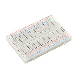
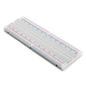
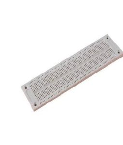
A breadboard is a fundamental tool used in electronics and prototyping that allows for the construction and testing of circuits without the need for soldering. It consists of a perforated plastic board with a grid of interconnected metal strips underneath, which provide a means to insert and connect electronic components such as resistors, capacitors, and integrated circuits. Breadboards are widely used in educational settings, hobbyist projects, and professional development due to their reusability and ease of use.
**Applications:**
1. **Prototyping:** Breadboards are primarily used for developing and testing new electronic circuits before finalizing a design.
2. **Educational Purposes:** They are extensively used in educational institutions to teach students about circuit design and electronics.
3. **Hobby Projects:** Enthusiasts and hobbyists use breadboards to create and experiment with various electronic projects.
4. **Testing and Debugging:** Engineers use breadboards to test and debug circuits in the development phase.
**Types:**
1. **Solderless Breadboards:** The most common type, which allows components to be easily inserted and removed without soldering.
2. **Stripboard (Veroboard):** A type of breadboard with parallel strips of copper, requiring soldering to make connections.
3. **Printed Circuit Breadboards:** These are pre-designed circuit boards that mimic the layout of a breadboard but require soldering.
**Working:**
A breadboard works by providing a grid of holes into which electronic components can be inserted. The holes are connected by metal strips underneath the board, forming a network of electrical connections. The board is typically divided into two sections: the main area for placing components and the power rails for distributing power. Components are placed in the main area, and connections are made by inserting wires into the appropriate holes, allowing for quick and flexible circuit assembly.

Introduction To Bread Boards: Understanding Their Purpose And Functionality
Breadboards are indispensable tools in the realm of electronics, serving as a foundational platform for prototyping and testing circuit designs. These versatile devices allow engineers, hobbyists, and students to experiment with circuit configurations without the need for soldering, thus facilitating a more efficient and error-free design process. Understanding the purpose and functionality of breadboards is crucial for anyone delving into electronics, as they provide a practical and flexible means to bring theoretical concepts to life.
At its core, a breadboard is a rectangular plastic board with a grid of tiny holes, each connected to metal strips underneath. These metal strips are arranged in a specific pattern to create electrical connections between inserted components. The primary purpose of a breadboard is to enable the construction of temporary circuits, allowing for easy modifications and adjustments. This is particularly beneficial during the initial stages of circuit design, where changes are frequent and the need for a non-permanent solution is paramount.
Transitioning to the types of breadboards, it is essential to recognize that they come in various sizes and configurations to suit different project requirements. The most common type is the solderless breadboard, which, as the name suggests, does not require soldering. This type is ideal for beginners and for projects that demand frequent reconfiguration. Solderless breadboards typically feature two sets of connected rows: the terminal strips and the bus strips. Terminal strips are used for placing components, while bus strips are designated for power supply connections.
Another type of breadboard is the solderable breadboard, which is used for more permanent projects. Unlike its solderless counterpart, this type requires components to be soldered onto the board, providing a more stable and durable connection. Solderable breadboards are often used in the final stages of a project, once the design has been thoroughly tested and validated.
Moving on to the working mechanism of breadboards, it is important to understand how the internal connections facilitate circuit assembly. When a component’s lead is inserted into a hole on the breadboard, it makes contact with the metal strip beneath, establishing an electrical connection. The metal strips are arranged in rows and columns, with each row typically connected horizontally and each column connected vertically. This grid-like structure allows for the creation of complex circuits by simply inserting and connecting various components such as resistors, capacitors, and integrated circuits.
Furthermore, breadboards often include power rails, which run along the sides of the board and provide a convenient way to distribute power to different parts of the circuit. These power rails are usually marked with positive and negative signs to indicate the polarity of the power supply. By connecting the power supply to these rails, users can easily power their entire circuit without the need for additional wiring.

In conclusion, breadboards are essential tools in the field of electronics, offering a flexible and efficient means to prototype and test circuit designs. Their ability to facilitate easy modifications and adjustments makes them invaluable for both beginners and experienced engineers. By understanding the different types of breadboards and their working mechanisms, users can effectively harness their potential to bring innovative electronic projects to fruition.
Different Types Of Bread Boards: A Comprehensive Guide
Breadboards are indispensable tools in the realm of electronics, providing a versatile platform for prototyping and testing circuits without the need for soldering. These boards come in various types, each tailored to specific applications and user requirements. Understanding the different types of breadboards is crucial for selecting the right one for your project, ensuring efficiency and accuracy in your electronic endeavors.
To begin with, the most common type of breadboard is the solderless breadboard. This type is widely used by hobbyists, students, and professionals alike due to its ease of use and reusability. Solderless breadboards feature a grid of interconnected holes into which electronic components can be inserted. The internal connections are typically made of metal strips that run beneath the board’s surface, allowing for quick and flexible circuit assembly. These breadboards come in various sizes, from small, compact versions suitable for simple circuits to larger ones that can accommodate more complex designs.
Transitioning to another popular type, we have the stripboard, also known as Veroboard. Unlike solderless breadboards, stripboards require soldering to create permanent connections. They consist of a grid of holes with parallel strips of copper running along one side. Users can cut these strips to isolate sections and create custom circuit paths. Stripboards are favored for more permanent projects where a stable and reliable connection is essential. They offer a balance between flexibility and durability, making them suitable for both prototyping and final product assembly.
Next, we encounter the perfboard, or perforated board, which is another type of breadboard that necessitates soldering. Perfboards are characterized by a grid of holes without any pre-existing connections. This design allows for complete freedom in creating custom circuit layouts. Users can place components anywhere on the board and connect them using wires or solder bridges. Perfboards are ideal for projects that require a unique or unconventional circuit design, providing maximum flexibility at the cost of increased assembly time and effort.
Moving on, we have the specialized breadboards designed for specific applications. For instance, Arduino-compatible breadboards are tailored to fit Arduino microcontroller boards, providing a seamless platform for developing and testing Arduino-based projects. These breadboards often include additional features such as power rails and pre-wired connections to simplify the integration of the microcontroller with other components.
Furthermore, there are breadboards with built-in power supplies, which offer a convenient solution for powering circuits directly from the board. These breadboards typically include voltage regulators and power connectors, allowing users to easily switch between different voltage levels and power their projects without the need for external power sources.
In addition to these types, there are also breadboards designed for high-frequency applications. These boards are constructed with materials and layouts that minimize signal interference and loss, making them suitable for radio frequency (RF) and microwave circuits. High-frequency breadboards are essential for projects that involve wireless communication, signal processing, and other applications where signal integrity is paramount.

In conclusion, the variety of breadboards available caters to a wide range of applications and user needs. From the versatile solderless breadboards to the customizable stripboards and perfboards, each type offers unique advantages and is suited to different stages of the prototyping and development process. Specialized breadboards further enhance functionality by addressing specific requirements, such as compatibility with microcontrollers or high-frequency performance. By understanding the different types of breadboards, users can make informed decisions and select the most appropriate tool for their electronic projects, ultimately leading to more efficient and successful outcomes.
How Bread Boards Work: A Step-By-Step Explanation
Breadboards are essential tools in the realm of electronics, providing a versatile platform for prototyping and testing circuits without the need for soldering. Understanding how breadboards work is crucial for anyone delving into electronics, whether they are hobbyists or professionals. This step-by-step explanation will elucidate the inner workings of breadboards, ensuring a comprehensive grasp of their functionality.
To begin with, a breadboard is a rectangular plastic board with a grid of holes, designed to accommodate electronic components and wires. The holes are arranged in a specific pattern, with rows and columns that facilitate the connection of components. The primary feature of a breadboard is its internal metal strips, which are hidden beneath the plastic surface. These metal strips are responsible for creating electrical connections between the inserted components.
When examining a breadboard, one will notice that it is divided into two main sections: the terminal strips and the bus strips. The terminal strips, located in the central area, consist of rows of interconnected holes. Each row is electrically isolated from the others, allowing for the placement of components such as resistors, capacitors, and integrated circuits. On either side of the terminal strips, the bus strips run vertically. These strips are typically used for power distribution, with one strip designated for the positive voltage and the other for the ground connection.
To illustrate the working of a breadboard, consider the process of building a simple LED circuit. First, the power supply is connected to the bus strips, ensuring that the positive and ground connections are established. Next, the LED is placed into the terminal strip, with its anode (positive leg) connected to the positive bus strip and its cathode (negative leg) connected to a resistor. The other end of the resistor is then connected to the ground bus strip. When the power supply is activated, current flows from the positive bus strip, through the LED and resistor, and finally to the ground bus strip, causing the LED to illuminate.
The versatility of breadboards extends beyond simple circuits. They are invaluable for testing and debugging more complex designs, as components can be easily added, removed, or rearranged without the need for soldering. This flexibility is particularly beneficial during the development phase, where modifications and adjustments are frequently required.
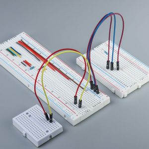
Moreover, breadboards come in various sizes and configurations to accommodate different project needs. The most common type is the full-size breadboard, which offers ample space for larger circuits. For smaller projects or space-constrained environments, mini and half-size breadboards are available. Additionally, some breadboards feature adhesive backing, allowing them to be securely mounted on a surface.
In conclusion, breadboards are indispensable tools for anyone involved in electronics. Their ability to facilitate rapid prototyping and testing, combined with their ease of use, makes them a staple in both educational and professional settings. By understanding the internal structure and working principles of breadboards, one can harness their full potential, paving the way for successful electronic projects.
Common Applications Of Bread Boards In Electronics Projects
Breadboards are indispensable tools in the realm of electronics, serving as the foundation for prototyping and testing circuits without the need for soldering. Their versatility and ease of use make them a staple in both educational settings and professional environments. Understanding the common applications of breadboards in electronics projects can provide insight into their significance and utility.

One of the primary applications of breadboards is in educational settings, where they are used to teach students the fundamentals of electronics. By allowing learners to construct and deconstruct circuits with ease, breadboards facilitate hands-on learning and experimentation. This practical approach helps students grasp complex concepts such as Ohm’s Law, Kirchhoff’s Laws, and the behavior of various electronic components like resistors, capacitors, and transistors. The ability to quickly modify circuits on a breadboard encourages exploration and fosters a deeper understanding of electronic principles.
In addition to educational purposes, breadboards are extensively used in the initial stages of product development. Engineers and designers rely on breadboards to prototype and test new circuit designs before committing to more permanent solutions like printed circuit boards (PCBs). This iterative process allows for rapid testing and debugging, enabling designers to identify and rectify issues early in the development cycle. Consequently, breadboards play a crucial role in reducing development time and costs, ultimately leading to more efficient and effective product development.
Moreover, breadboards are invaluable tools for hobbyists and makers who engage in DIY electronics projects. Whether building a simple LED circuit or a more complex microcontroller-based system, breadboards provide a flexible platform for experimentation. The ability to easily add, remove, and rearrange components makes breadboards ideal for iterative design and testing. This flexibility is particularly beneficial for those who may not have access to advanced tools and equipment, allowing them to bring their creative ideas to life with minimal investment.
Another significant application of breadboards is in the testing and troubleshooting of existing circuits. When a circuit malfunctions, engineers can replicate the problematic sections on a breadboard to diagnose and resolve issues. This approach is especially useful when dealing with intricate or densely packed PCBs, where direct probing and modification can be challenging. By isolating and testing specific components or sections on a breadboard, engineers can efficiently identify faults and implement corrective measures.
Furthermore, breadboards are often used in conjunction with other prototyping tools and platforms, such as Arduino and Raspberry Pi. These microcontroller and single-board computer platforms are popular among both professionals and hobbyists for developing a wide range of applications, from simple automation projects to complex IoT systems. Breadboards provide a convenient interface for connecting sensors, actuators, and other peripherals to these platforms, enabling rapid prototyping and testing of various configurations.
In conclusion, the common applications of breadboards in electronics projects underscore their importance as versatile and practical tools. From educational settings to professional product development, hobbyist projects, and troubleshooting, breadboards facilitate hands-on experimentation, rapid prototyping, and efficient problem-solving. Their ability to accommodate a wide range of components and configurations makes them an essential asset in the toolkit of anyone involved in electronics. As technology continues to evolve, the role of breadboards in fostering innovation and creativity remains as vital as ever.
Tips And Tricks For Using Bread Boards Effectively In Your Projects
When working on electronic projects, breadboards are indispensable tools that allow for the rapid prototyping and testing of circuits without the need for soldering. To maximize the effectiveness of breadboards in your projects, it is essential to understand some tips and tricks that can streamline your workflow and enhance the reliability of your circuits.
First and foremost, it is crucial to plan your circuit layout before placing any components on the breadboard. This planning phase can save you considerable time and effort by preventing the need for frequent adjustments. Sketching a rough diagram of your circuit on paper or using software tools can help you visualize the connections and component placements, ensuring a more organized and efficient setup.
Another important tip is to use color-coded wires for different types of connections. For instance, you might use red wires for power connections, black wires for ground, and other colors for signal lines. This practice not only makes your circuit easier to understand at a glance but also reduces the likelihood of errors during assembly and troubleshooting.
When inserting components into the breadboard, ensure that the leads are straight and properly aligned with the holes. Bent or misaligned leads can cause poor connections, leading to intermittent or unreliable circuit behavior. Additionally, avoid placing components too close to each other, as this can make it difficult to identify and access individual parts, especially when making adjustments or debugging.
To maintain a clean and organized workspace, it is advisable to trim excess wire lengths after making connections. Long, looping wires can create a tangled mess that is difficult to manage and can introduce noise or interference into your circuit. Using wire cutters to trim wires to the appropriate length not only improves the aesthetics of your breadboard but also enhances the overall performance of your project.
One common issue encountered when using breadboards is the potential for loose connections. To mitigate this, ensure that all components and wires are firmly seated in the breadboard holes. If you notice any loose connections, gently press down on the component or wire to secure it in place. In some cases, it may be necessary to replace the breadboard if the contacts have become worn or damaged over time.
When working with integrated circuits (ICs), it is beneficial to use IC sockets rather than inserting the ICs directly into the breadboard. IC sockets provide a more secure connection and protect the ICs from potential damage caused by repeated insertion and removal. Additionally, using IC sockets allows for easy replacement of ICs without disturbing the rest of the circuit.
To further enhance the reliability of your breadboard projects, consider using power rails for distributing power and ground connections. Most breadboards come with built-in power rails along the sides, but if your breadboard does not have them, you can create your own using jumper wires. Power rails simplify the process of connecting multiple components to the power supply and help maintain a clean and organized layout.
Finally, it is essential to test your circuit thoroughly before moving on to the next stage of your project. Use a multimeter to check for continuity and verify that all connections are secure. Additionally, power up your circuit gradually, starting with a lower voltage if possible, to ensure that there are no short circuits or other issues that could damage your components.
By following these tips and tricks, you can effectively utilize breadboards in your electronic projects, leading to more efficient prototyping, easier troubleshooting, and ultimately, more successful outcomes.
Conclusione
A breadboard is a construction base used for prototyping electronics. It allows for the creation and testing of circuit designs without soldering, making it reusable and ideal for experimentation. Breadboards are commonly used in educational settings, hobbyist projects, and initial stages of product development. They come in various types, including solderless breadboards, which are the most popular, and solderable breadboards for more permanent setups. The working principle involves inserting electronic components and connecting them through a grid of interconnected holes and metal strips, facilitating easy modifications and troubleshooting.
